Edit Array
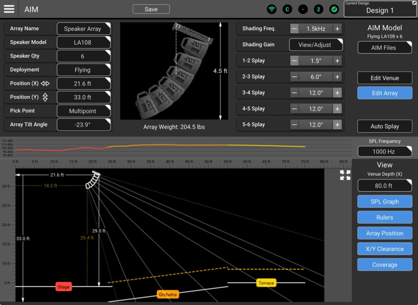
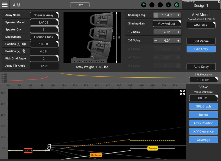
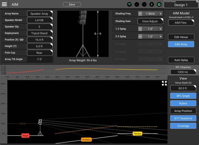
The Edit Array area of AIM![]() Array Installation Modeling (AIM) is a QSC System Navigator prediction tool used for visualization of array coverage in a scaled, graphical model of a venue or installation space. AIM also provides dimensional and weight data for an array as well as pick-point recommendations. is used to select an L Class loudspeaker model, specify the quantity of loudspeakers in the array and make deployment selections. These selections, combined with the Venue model provide a visualization of the array coverage.
Array Installation Modeling (AIM) is a QSC System Navigator prediction tool used for visualization of array coverage in a scaled, graphical model of a venue or installation space. AIM also provides dimensional and weight data for an array as well as pick-point recommendations. is used to select an L Class loudspeaker model, specify the quantity of loudspeakers in the array and make deployment selections. These selections, combined with the Venue model provide a visualization of the array coverage.
-
Array Name – Select the field to enter a name for the array.
-
Speaker Model – Touch/click to display a dropdown menu where AIM compatible loudspeakers may be selected.
-
Speaker Qty – Touch/click to display a dropdown menu where the quantity of loudspeakers may be specified.
-
Deployment – Touch/click to display a dropdown menu where deployment options may be selected. Deployment selection affects other available array controls. See the Deployment section below for details on each option.
-
Position (X) – When the field is selected, the keypad may be used to input the horizontal distance from the origin point.
Note: The array position may also be changed by dragging the array icon in the venue model.
-
Position (Y) – When the field is selected, the keypad may be used to input the vertical distance from the origin point. The keypad nudge buttons may also be used to nudge the array.
Note: The array position datum point will vary depending on deployment:
• Flying array – Middle of the upper edge of the topmost loudspeaker.
• Pole or speaker stand – Top of the pole cup.
• Ground stack – Lower front corner of the stack adapter. -
Array Graphic (Upper Center) – Depicts a side view of the array in a flying, ground-stacked or tripod mounted deployment.
-
Shading Freq. – Displays and selects the HF (High-Frequency) shading frequency for the array.
-
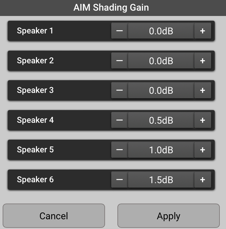
Shading Gain – Displays and adjusts the gain for the HF Shading
 Generally, it is good practice to have the same signal processing parameters applied to all loudspeakers in an array. Array Shading is an exception. Array Shading is accomplished by adjusting the high-frequency output level of individual array loudspeakers relative to others in order to achieve a desired frequency balance across the listening area..
 Example: Shading Gain Controls
 -
Splay
The angle between two adjacent loudspeakers in an array. – Clicking - or + adjusts the angle between two adjacent loudspeakers. (Note that the angle between the array frame and the topmost loudspeaker is not adjustable.)
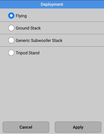
Deployment
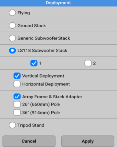
The Deployment selection determines how the array is configured and placed. Options are:
-
Flying
-
Ground Stack
-
Subwoofer Stack (includes additional choices)
-
Tripod Stand
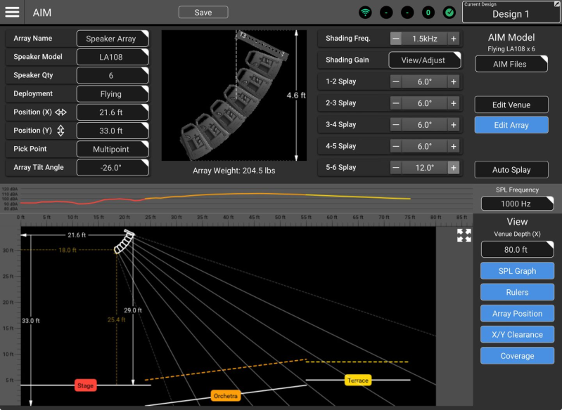
Flying
The array will be displayed with its array frame at the top.
-
Pick Point
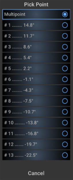
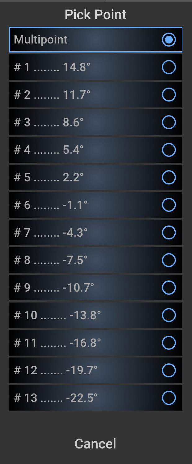
When suspending a loudspeaker array, pick point refers to the point (or points) where the rigging hardware is attached to the array frame mounted at the top of the array. – This function defines how the array is to be suspended. Click the field to see the  Pick Point dropdown menu:
-
Multipoint – When this options is selected, the user may specify the desired tilt angle using the Array Tilt Angle field below.
-
#1 to #13 (single pick point) – The L Class array frame provides 13 attachment points. AIM calculates and displays a tilt angle based on the specified array configuration. If deployment using a single point of attachment is to be used, select the point that comes closest to providing the desired tilt angle. There are limitations to the tilt angles that can be achieved using a single pick point. For those applications a multipoint hang is required.
Note: In the real world, parameters such as the weight of electrical cabling or other suspension hardware can affect the tilt angle of a physical array using a single pick-point. AIM does not account for these factors.
-
-
Array Tilt Angle – If the Pick Point selection is “Multipoint”, this field is used to input and/or indicate the array tilt angle. A tilt of 0° indicates that the fly-bar and the horizontal axis of the top loudspeaker in the array is parallel to the ground. A negative number indicates the array is tilted down.
Tip: The array tilt angle may also be adjusted by dragging the coverage pattern beams in the model.
-
Array Image – The array is depicted in a side view.
-
The dotted line indicates the array’s center of gravity.
-
The arrow line indicates the overall height of the array.
-
The total weight of the array speakers plus the array frame will be displayed below the depiction of the array. The weight of cables and other rigging hardware is not included in this calculation.
-
Ground Stack
The array will be displayed on top of the Array Frame (LA108-AF or LA112-AF) and Stack Adapter (LA108-KIT-SA or LA112-KIT-SA).
-
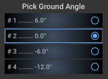
Pick Grnd (Ground) Angle – The Stack Adapter supports array tilt angles of 6°, 0°, -6°, and -12°. A selection dialog will appear.
-
Array Tilt Angle – This field is read-only and is determined by the Pick Ground Angle selection described above.
Tripod Mount
The array is displayed on top of a tripod that extends to the supporting surface.
Height — The height range setting is limited to 3 - 6 feet (.9 - 1.8 meters).
Pole Cup — L Class loudspeakers provide pole sockets that support array tilt angles of 0° and -7.5°
Array Tilt Angle — This field is read-only and is determined by the Pole Cup selection described above.
Subwoofer Stack
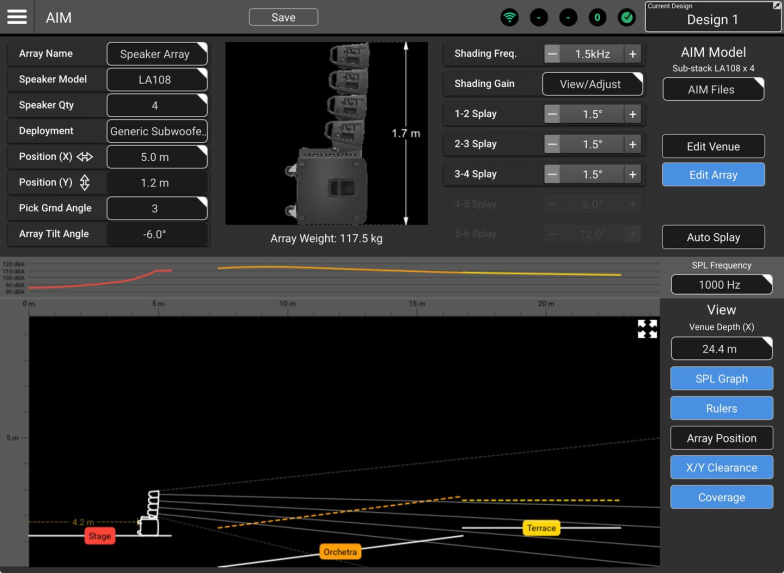
Selection of a generic or LS118 Subwoofer Stack determines the elevation of the array but, other than that has no effect on AIM coverage calculations. Two primary subwoofer options are provided:
-
Generic Subwoofer Stack - Positions the array on top of a generic subwoofer or subwoofers. The subwoofer dimensions are typical of commonly-used single 18-inch models.
-
LS118 Subwoofer Stack - Positions the array on top of an LS118 subwoofer or subwoofers. If the Inventory
The devices that are part of a design. An Inventory device may be virtual or physical. “Import From AIM” function is used, the LS118 subwoofer(s) will be brought into the Inventory along with the array.
Subwoofer Deployment Options
The subwoofer dimensions are typical of commonly-used single 18-inch models.
-
Quantity — 1 or 2 subwoofers may be selected.
-
Deployment
-
Vertical — The subwoofer height is approximately 25 inches (635 mm).
-
Horizontal — The subwoofer height is 20 inches (508 mm).
-
-
Array Frame & Stack Adapter or Pole — Renders a model with the selected array attachment hardware.
-
Pick Grnd (Ground) Angle – The Stack Adapter supports array tilt angles of 6°, 0°, -6°, and -12°. A selection dialog will appear.
-
Array Tilt Angle – This field is read-only and is determined by the Pick Ground Angle selection described above.
Unsupported Deployment
There are two potential conditions that will display an Unsupported Deployment message.
-
Convoluted Array
An array in which the splay angle between adjacent array members is smaller than the splay angle between boxes located higher in the array. — Optimum deployment of an L Class loudspeaker array requires that each splay angle be equal to or greater than the splay angle above it. Any other deployment results in a “broken” or “convoluted” array. -
Unsafe Deployment — A ground stack, subwoofer stack or tripod mount should only be located on a level surface. If one of these arrays is positioned over a tilted audience area, the Unsupported Deployment message will appear and the array loudspeakers will be displayed in red.

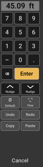
Keypad
The keypad is used for entry of numeric values. It appears whenever a value field is selected. The keyed-in value is entered into the AIM model when the Enter key is touched or clicked. If the device that’s running SysNav has a keyboard, it may also be used for numeric value entry. Other controls include:
|
|